What Are Organic Solar Cells and How Do They Work

As the interest in renewable energy sources increases, research on alternative technologies beyond traditional solar or wind power finds their spotlight for innovation. The solar energy market has majorly been dominated by silicon solar panels, where we see acres of land covered with solar panel farms. However, the bulky, rigid and heavy physical characteristics of silicon solar panels limit their application in areas that demand more versatile solutions. These limitations open the door for alternative technologies like organic solar cells (OSCs), which offer a flexible and lightweight product. Their flexibility and low weight make OSCs suitable for novel applications like wearable electronics, building-integrated technology, and portable devices. To understand the attraction this technology has gained and the challenges it faces, we need to dive into their structure and how they do operate.
The Organic Solar Cell Device Design
A typical organic solar cell device is made of:
Active Layer: The core layer, consisting of an organic semiconductor, which absorbs light. When light is absorbed, excitons (closely bound pairs of electrons and holes) can be generated.
Interlayers: Additional layers to help electrons and holes separate easily and efficiently. Inserted between the active layer and the electrodes.
Electrodes: Corresponding positive and negative contacts to collect electrons and holes. At least one of these is required to be transparent.
Substrate: where the device is built on, such as glass or plastic

Figure 1. Device design of organic solar cells.
Active Layer
Organic Semiconductor: Bandgaps, HOMO, LUMO
Materials can be classified based on their band gap (Eg), which defines the energy difference between the highest occupied molecular orbital (HOMO), or conduction band, and the lowest unoccupied molecular orbital (LUMO), or valence band. In metals, both bands are partially filled with electrons, resulting in no energy gap between the highest occupied level, known as the Fermi level, and the lowest vacant level.
Semiconductors and insulators, on the other hand, have defined band gaps. Insulators are typically characterized by a relatively high band gap, making them poor conductors of electricity. Semiconductors fall in between metallic conductors and insulators.
The semiconducting materials used in the active layer of an organic solar cell play a crucial role in converting the device into a functioning solar cell. Organic semiconductors for OSCs, typically conjugated polymers or small molecules are carefully chosen for their molecular properties, as this determines the material’s ability to absorb light and thereby enables the generation of charges which ultimately provide electricity.
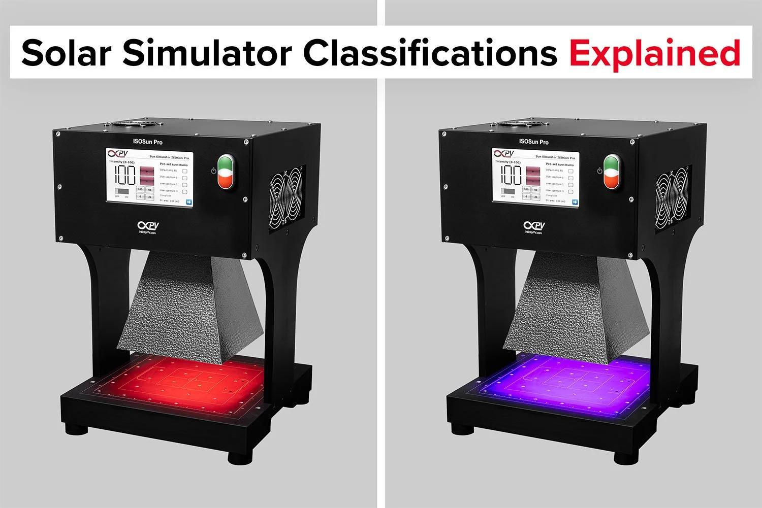
How to test solar cells using a source measure unit and solar simulator.
When a photon is absorbed by the active layer, energy is provided to the absorbed material. If the energy absorbed is equal to or greater than the bandgap, excitation can occur as an electron moves from HOMO to LUMO. However, excitation cannot occur if the absorbed energy is lower than the bandgap. Consequently, materials with a high bandgap can only absorb photons (light) with high energy whereas materials with a lower bandgap can absorb both the high energy photons and photons with lower energy. Low bandgap materials can hence absorb more photons, which in a solar cell means that there potentially are more charges to extract. From a solar cell perspective more charges sound like an ideal situation but the higher number of charges comes with a tradeoff as they will all have less energy than the charges generated in a high bandgap material. Finding materials that have a high absorption of light, and an acceptable potential energy of the generated charges is where organic semiconductors show their potential as organic materials are easily modified/tunable in the quest for the optimal materials. Therefore, in OSCs, organic semiconductors play a versatile role since the bandgap can be optimized to maximize light absorption and device efficiency.

Figure 2. Representation of HOMO, LUMO and Bandgap as energy levels.
Bilayer and Bulk Heterojunction
One of the challenges in OSC devices is the separation of the charges of the closely bound electron/hole pair in the formed exciton, as it will recombine (the excited electron drops from the LUMO to the HOMO, releasing energy) with no charge extractions as a result. One way to separate excitons into free electrons and free holes is by introduction of a heterojunction, where one material is energetically favorable for electron transport and the other for hole transport. Often the material with high hole affinity is called the donor and the material with high electron affinity is called the acceptor. If a generated exciton can diffuse to the donor/acceptor interface, the charges can potentially be separated with the electron going to acceptor and the holes to the donor. The now separated charges can then be transported to the electrodes.
Using a slot-die coater, you can create an organic solar cell with slot-die coating and flexo printing, ensuring precision, uniformity, and scalability.
Early organic solar cells used a bilayer heterojunction, where the donor and the acceptor were stacked on top of each other. However, this approach had limitations as most excitons are generated too far away from the donor/acceptor interface for them to diffuse to this before they decay.
To solve this issue, an alternate design was developed called the Bulk Heterojunction, in which an intimately connected network of donor and acceptor materials is created by blending them in the active layer. This structure increases the contact area between the two materials, creating an interpenetrating network. This network leads to an easier pathway for excitons to separate into electrons and holes as rapidly as possible, thus increasing the efficiency significantly. The bulk heterojunction also allows for thicker active layer coatings compared to bilayer devices.

Figure 3. Interfacial between bilayer and bulk heterojunction.
Interlayers
The pathway of electrons and holes towards their respective electrodes depends on the difference in energy levels between materials. Looking at the bulk heterojunction, there is no apparent difference between the top and the bottom of the active layer, and there is therefore no direct driving force for electrons to go to one electrode and the holes to the other. Charge selective interlayers between the active layer and the electrodes are therefore used as promoters for the flow of charges. OSCs commonly use PEDOT:PSS as the Hole Transport Layer, and materials such as zinc oxide (ZnO) or titanium dioxide (TiO2) for the Electron Transport Layer.
Electrodes
The electrodes are the contacts of a device where either the positive or negative charges are collected. Besides the selectivity from the interlayers some additional selectivity can be achieved from electrodes energy threshold to extract electrons, called its work function. In general, the electron-collecting electrode should have a lower work function than hole-collecting electrode to attract electrons and holes, respectively
In addition to this, electrode selection also highly depends on other factors such as electrical conductivity, optical transparency and cost. Transparency of at least one of the electrodes is crucial to allow light to enter the solar cell. The most common transparent electrode is Indium Tin Oxide (ITO). Other commonly used electrodes include metals such as silver or aluminum.
Normal and Inverted Geometry
There are two different geometries to stack OSC device layers, based on the placement and the role of the electrodes. Conventionally, the ‘normal’ geometry of OSCs collects holes at the transparent electrode (front electrode) and electrons at the back electrode. As the name implies the collection is swapped in the ‘inverted’ geometry OSCs as they collect electrons at the front electrode and holes at the back electrode.

Figure 4. Device layers of normal and inverted geometry for OSCs.
How do Organic Solar Cells work?
At their core, OSCs operate by absorbing light and converting it into electrical energy just as every solar cell device does. More specifically, the mechanism happening in OSCs from light to electron conversion follows four fundamental steps.
Absorption of energy from sunlight in the donor material, creating excitons.
Diffusion of excitons to the Donor-Acceptor interface before they lose energy. The electron-hole pair is bound to each other by Coulombic forces and their diffusion through the active layer is coupled.
At the interface between the donor and acceptor materials, excitons split into free electrons and holes, resulting in a positively charged hole remaining in the donor while the negatively charged electron is transferred to the acceptor material.
Collection of electrons and holes at their respective electrode, generating electricity.
When the excitons are separating into holes and electrons, the holes follow the path on HOMO energy level while electrons continue their way on LUMO energy level. It is energetically favorable for the electrons generated in the donor material to move from the LUMO of the donor to the lower-energy LUMO of the acceptor. For efficient separation of excitons, it is essential to have an appropriate energy offset between the LUMO levels of the two materials. Interlayers create a mid-step between the active layer and electrodes, and the energy level pathway can be illustrated like this;

Figure 5. Working mechanism of organic solar cells represented in energy levels.
Conclusion
OSCs operate through a different working mechanism than inorganic solar cells, consisting of layers which can be optimized according to desired optical and mechanical properties. The tunability of organic semiconductors of OSCs offers targeted material design, bringing significant potential for enhanced light absorption, energy conversion and device efficiency. Furthermore, innovations like bulk heterojunctions and versatile device geometries demonstrate that OSC performance can be significantly improved not only through molecular design but also through structural advancements. These features place OSCs as a promising technology for applications requiring lightweight, flexible, and adaptable solar solutions.
Learn More About Organic Solar Cells
Ahmad, N., Zhou, H., Fan, P., & Liang, G. (2022). Recent progress in cathode interlayer materials for non‐fullerene organic solar cells. EcoMat, 4(1), e12156.
Heeger, A. J. (2014). 25th anniversary article: bulk heterojunction solar cells: understanding the mechanism of operation. Advanced materials, 26(1), 10-28.
Su, Y. W., Lan, S. C., & Wei, K. H. (2012). Organic photovoltaics. Materials Today, 15(12), 554-562.

About the Author
Ümran Işıl Biçer is a Marie Curie PhD fellow at infinityPV, contributing to the Marie Skłodowska-Curie EIFFEL project. She received her bachelor’s degree from Middle East Technical University in Turkey and completed her master’s through the Erasmus Mundus MaMaSELF program, studying at Ludwig Maximilian University of Munich and the University of Montpellier, with her thesis conducted at the University of Helsinki. She is pursuing a PhD in the development of non-fullerene acceptors for organic solar cells, focusing on scalable roll-to-roll printing methods to improve solar cell efficiency and stability.
Related Articles


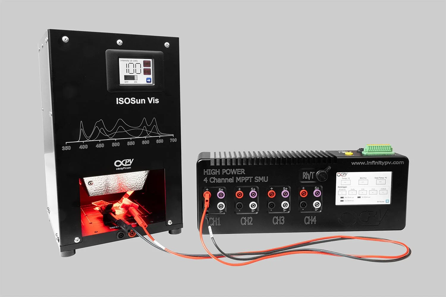
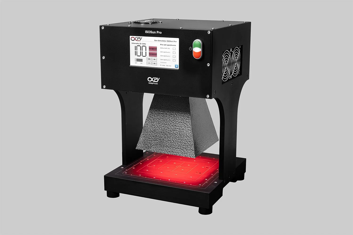
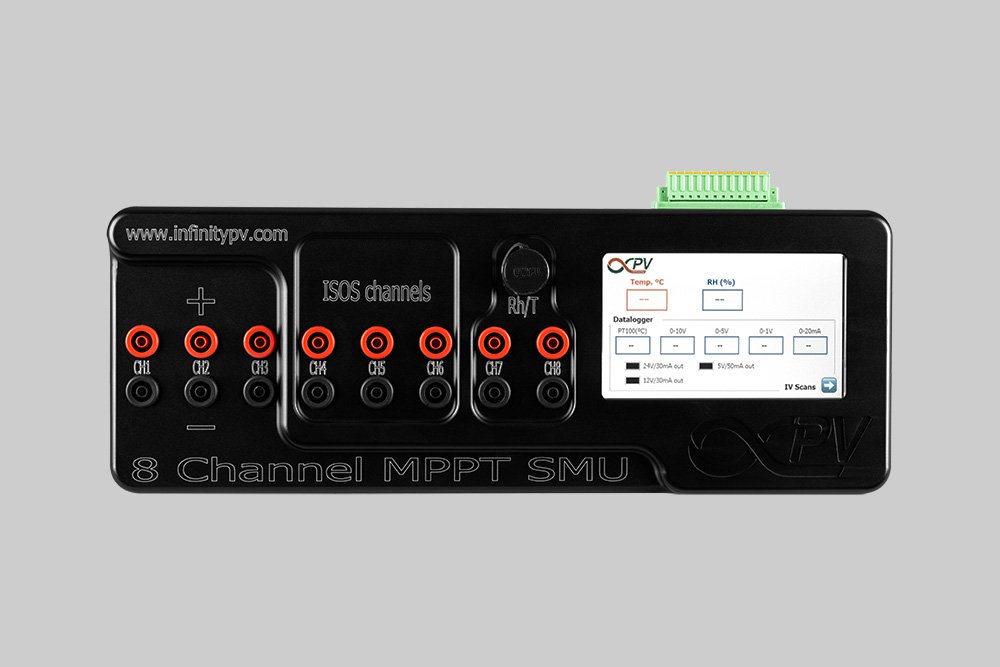


Get started with solar cell research with a complete, ready-to-use system. This bundle combines a compact Solar Simulator and an 8 Channel Source Measure Unit to make PV characterization easy and accessible.